Linux mdadm software RAID vs Broadcom MegaRAID 9560

In the past years I’ve said goodbye to hardware RAID controllers and mainly relied on software solutions like mdadm, LVM, Ceph and ZFS(-on-Linux) for keeping data safe.

At PCextreme we use hypervisors with local NVMe storage running in Linux’s mdadm software RAID-10. This works great! But I wasn’t satisfied with the performance for a few reasons:

  • It is expensive on the CPUs (Dual AMD Epyc 48-core)
  • It’s not super fast

We mainly use the Samsumg PM983 (1.92TB) devices and I started to look around if there is a hardware solution which could offload the RAID computation to a dedicated SoC so it wouldn’t eat up our CPU cycles.

After searching I found the Broadcom SAS3916 chip which is on the MegaRAID 9516-16i controller from Broadcom. This chipset supports NVMe devices in various RAID modes.

I wanted to benchmark Linux’s software RAID against the Broadcom controller to see if it would be faster and save us the expensive CPU cycles.

With mdadm we also looked into RAID-5/6 to have more usable space. We however found out that this eats up so many CPU cycles that it wasn’t feasible to use in production for our purposes.

Benchmarking setup

  • Ubuntu Linux 18.04 with kernel 5.3
  • SuperMicro 1114S-WN10RT
  • AMD Epyc 7302P 16-core CPU
  • 128GB Memory
  • 4x Samsung PM983 1.92TB
  • Broadcom MegaRAID 9516-i

Benchmarking will be done using fio and the main elements we are looking for:

  • QD=1, 4, 8 and 16 4k random write performance
  • CPU utilization during benchmarks

MegaRAID configuration

The RAID-10 array was created using storcli

storcli64 /c0 add vd type=raid10 drives=252:4,6,8,10 pdperarray=2

mdadadm setup

RAID-10 was set-up using this command:

mdadm --create --level=10 --raid-devices=4 /dev/md0 /dev/nvme0n1 /dev/nvme1n1 /dev/nvme2n1 /dev/nvme3n1

fio

The fio jobs we ran to benchmark:

[global]
ioengine=libaio
direct=1
invalidate=1
bs=4k
runtime=300
filename=/var/lib/libvirt/images/fio
size=64g
rw=randwrite
numjobs=1

[rw_mdadm_1]
iodepth=1

[rw_mdadm_4]
iodepth=4

[rw_mdadm_8]
iodepth=8

[rw_mdadm_16]
iodepth=16

[rw_mdadm_32]
iodepth=32

Results

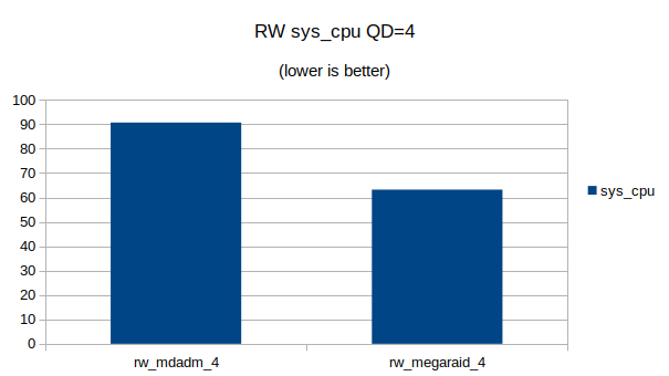
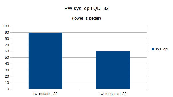
Short answer? The MegaRAID controller is much faster in RAID-10 mode and also saves up to 30% of CPU cycles on the Linux machine.

You can also download the JSON output from fio here:

In addition you can download my Open Office spreadsheet I used to generate the graphs and process the data.
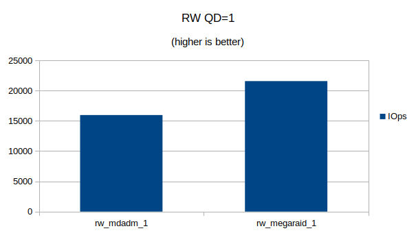
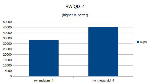
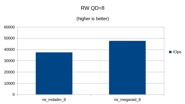
Graphs

Some graphs with the results of the IOps and CPU utilization.

At QD 16~32 we seem to have found the upper limit of what the 4 NVMe devices are capable of. Going from QD 16 to 32 does not make a significant difference.
At QD32 we can still see that the MegaRAID controller uses a lot less CPU cycles then Linux’s software RAID

1Gbit fiber connection between MikroTik and Unifi switch

While replacing my router at home by a MikroTik CCR1036-8G-2S+ router I also wanted to uplink my Ubiquity switch using a Multimode (OM3) connection.

Is fiber really needed? Not really, but it saved me an additional RJ45 port on my switch which allows me to connect more.

Link up, down, up, down

The link between my MikroTik router and Unifi switch kept going up and down. In the logs on my MikroTik and Unifi switch I saw:

<14> May 26 19:19:07 SwitchPatchkast DOT1S[dot1s_task]: dot1s_sm.c(314) 454679 %% Port (26) inst(0) role changing from ROLE_DESIGNATED to ROLE_DISABLED
<14> May 26 19:19:07 SwitchPatchkast DOT1S[dot1s_task]: dot1s_sm.c(314) 454677 %% Port (26) inst(0) role changing from ROLE_DISABLED to ROLE_DESIGNATED
<13> May 26 19:19:07 SwitchPatchkast TRAPMGR[trapTask]: traputil.c(743) 454676 %% Link Up: 0/26
<14> May 26 19:18:58 SwitchPatchkast DOT1S[dot1s_task]: dot1s_sm.c(314) 454668 %% Port (26) inst(0) role changing from ROLE_DESIGNATED to ROLE_DISABLED
<13> May 26 19:18:58 SwitchPatchkast TRAPMGR[trapTask]: traputil.c(743) 454667 %% Link Down: 0/26
19:25:12 interface,info sfp-sfpplus1 link up (speed 1G, full duplex)
19:25:20 interface,info sfp-sfpplus1 link down
19:25:21 interface,info sfp-sfpplus1 link up (speed 1G, full duplex)
19:25:29 interface,info sfp-sfpplus1 link down
19:25:30 interface,info sfp-sfpplus1 link up (speed 1G, full duplex)
19:28:48 interface,info sfp-sfpplus1 link down

I am using optics from FlexOptix which I programmed to MikroTik and Ubiquity using their programmer. (We have those at work).

Auto negotiation

After trying many things it turned out that turning off Auto Negotation on both the switch and the router resolved the issue.

On the switch I turned it off via the UI of the Unifi Controller and forced it to 1000 FDX.

On the router I turned it off using the MikroTik CLI:

[admin@router] > /interface ethernet export
/interface ethernet
set [ find default-name=sfp-sfpplus1 ] advertise=1000M-full auto-negotiation=no speed=1Gbps
set [ find default-name=sfp-sfpplus2 ] advertise=1000M-full speed=1Gbps
[admin@router] >

sfp-sfpplus1 is the interface I am using for the connection to my Unifi switch.

Link is now online! Below is a picture of my 19″ rack at home.

Exploring the CAN bus of my Tesla Model S

The CAN bus of a Tesla vehicle can show some interesting information about the state of different components in the vehicle.

Using a CAN bus cable, Bluetooth adapter and a App on your mobile phone you can gain much more insight on your Tesla vehicle.

I own two Tesla vehicles:

  • S85 from September 2013 (pre face-lift)
  • S100D from September 2018

Somewhere around 2015 Tesla switched to a different connector for the CAN bus so I needed two different cables. I bought my cables in Germany at EMDS.

EMDS also sells a cable for Model 3. I haven’t used this one as I don’t own a Model 3.

The CAN bus connector in a Model S can be found under the MCU’s main screen in the vehicle. You need to pull down the ‘chubby’ and there you will find the connector:

Cable connected to my Model S85

I am using the TM-Spy app on iOS for reading the values on my iPhone.

Screenshot of TM-Spy on iOS

For Android there is Scan My Tesla which also seems to be a very good app. I don’t have an Android device, so I was not able to test it.

I was mainly looking for these values:

  • Usable Full
  • DC Charge Total
  • AC Charge Total

After 253.543km of driving my battery has 75.6kWh of remaining capacity where this was ~81kWh when it was new. (The 85kWh battery was actually a 81kWh battery….)

Tesla also throttles a vehicle’s SuperCharging capabilities after more than X amount (I don’t know the exact value) of DC charging. My car seems to be affected as I SuperCharged a lot.

Charge Total is not a total sum of AC+DC, but from what I’ve read early firmwares did not count AC and DC charging in different values.

Interesting information though! I encourage everybody to use this information to gather more information about their vehicle’s state.

Happy exploring!