Waarom een Type 2 laadstation en geen Rode CEE voor een Model S?

For the international readers: The Tesla Model S comes with a Universal Mobile Connector which allows you to plug into any outlet. That’s useful for situations where you really, really, really need a charge, but I don’t think it’s a good and safe idea to use it for your every day charging.

This post is focused on the Dutch and Belgian readers so I’ll continue this post in Dutch.


Bij de Model S wordt een Universal Mobile Connector (UMC) geleverd waarmee je de Model S thuis kan opladen aan een Rode CEE 3-fase 16A.

Ik vind dit geen verstandige keuze van Tesla vanwege meerdere redenen die ik hier onder uiteen zal zetten.

De Rode 16A CEE

Deze komen we ongemerkt in ons dagelijks leven vaak tegen. Ze worden voor veel toepassingen gebruikt, maar ze zijn vooral te vinden bij bedrijven.

Ze zien er als volgt uit:

Red CEE 16A Wallmount

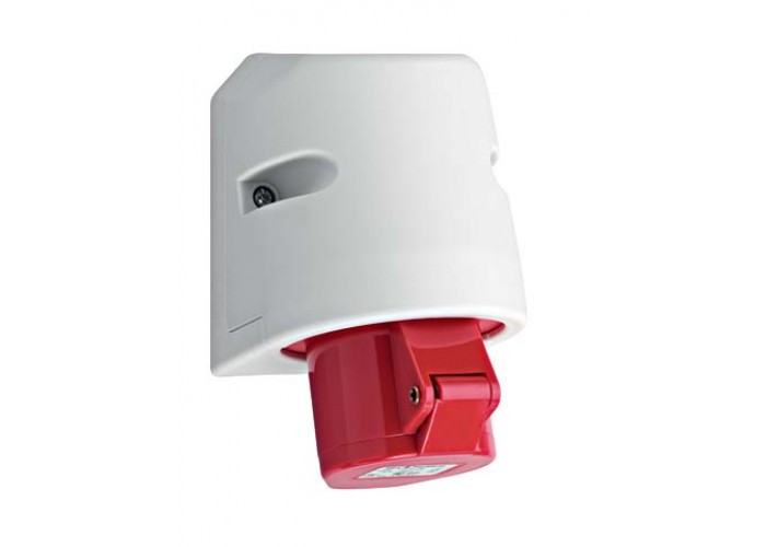
Een dergelijke aansluiting levert maximaal 16A bij 3-fase 400V. Ze bestaan ook in een 32A versie, echter kan een Model S daar niet aan opladen. (Elektrische normen verbieden dit).

3-fase 16A is 11kW aan vermogen. Een Model S kan aan deze aansluiting dus met 11kW opladen waardoor een 85kWh accu in ongeveer 8 uur weer vol is.

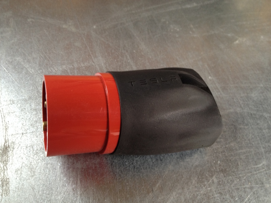
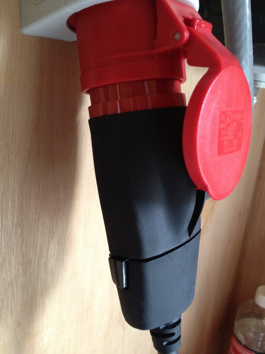
De geleverde UMC van Tesla verbindt je met deze adapter met de CEE aansluiting:

Tesla Model S UMC CEE Adapter

Als deze met de UMC verbonden is ziet het er zo uit:

Tesla Model S EU UMC Red CEE

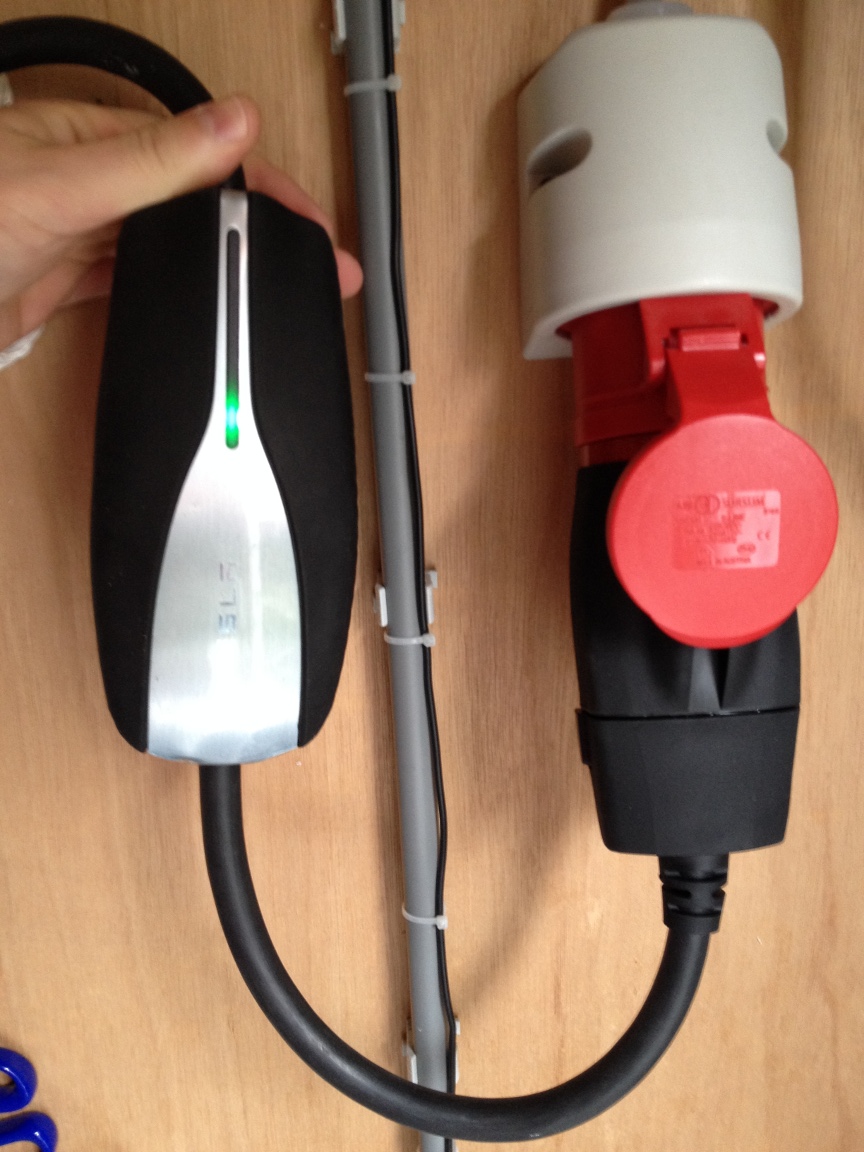
Zo ver ziet het er allemaal prima uit, echter is dit naar mijn mening geen veilige oplossing, hoewel dit op het eerste gezicht wel zo lijkt.

Waarom niet veilig?

Indien de aansluiting goed verbonden is sluit alles netjes aan:

Tesla Model S Red CEE Proper Insert

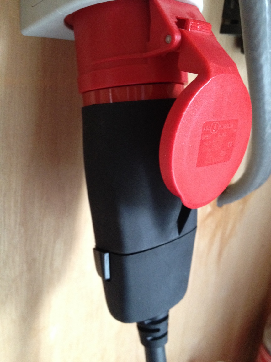
Dat ziet er allemaal prima uit, totdat we een beetje aan de kabel trekken en kijken wat er dan gebeurd:

Tesla Model S Red CEE Wrong Insert

Het ontbreken van vergrendeling
De aansluiting maakt nu nog steeds contact waardoor het laden van de auto nog door zal gaan, echter maken de pinnen in de aansluiting minder goed contact wat kan leiden tot meer warmte ontwikkeling.

Vergeet niet dat er 11kW aan vermogen door deze aansluiting gaat. 11kW staat gelijk aan 11 waterkokers die op vol vermogen aan het verwarmen zijn.

Deze CEE aansluitingen hebben een zeer beperkte vorm van vergrendeling. Het klepje van het aansluiting zou de stekker in de aansluiting moeten houden, maar zoals hier te zien is zit daar nogal wat speling op.

Hoewel deze aansluitingen in de bouw op grote schaal gebruikt worden, worden ze niet onder een continue vollast van 11kW gebruikt voor periodes van 8 uur achter elkaar. Ovens in bakkerijen werken hier ook op, echter gebruiken deze niet voor 8 uur achter elkaar het volle vermogen van de aansluiting en daar zit het probleem.

Het ontbreken van een correcte vergrendeling is hier dus een gevaar wat potentieel tot smelten van de aansluiting kan leiden.

Slijtage van de aansluiting
Dit valt ook samen met de vergrendeling, maar wil ik toch apart noemen.

Niet iedereen die elektrisch gaat rijden is even goed op de hoogte van electra. Het gevaar bestaat dat iemand terwijl de auto aan het laden is de rode stekker uit de aansluiting trekt omdat hij of zij moet gaan rijden. Dit is een moordaanslag op de aansluiting.

We hebben allemaal wel eens de stofzuiger uit het stopcontact getrokkken terwijl deze aan staat. Dit geeft al een flinke vonk in het stopcontact, maar dat is dan nog maar 1 tot 2kW aan vermogen, bij een auto spreken we over 11kW aan vermogen.

Dit zal een goede vonk opleveren binnen in de aansluiting die voor ons niet altijd direct zichtbaar zal zijn. De aansluitpinnen lopen hierdoor echter flinke schade op waardoor hun contactoppervlakte afneemt. De volgende keer dat er geladen wordt met de zelfde aansluiting zal minder oppervlakte zijn om het zelfde vermogen over te dragen wat tot extra warmte ontwikkeling zal leiden door de extra weerstand die in de aansluiting ontstaan is.

Het zal dus niet direct tot een probleem leiden, maar langzaam aan wordt de aansluiting van steeds mindere kwaliteit waarna het op een gegeven moment compleet fout gaat.

Altijd onder spanning
Een rode CEE aansluiting kent geen intelligentie en zal dus altijd onder spanning staan. Dit is een potentieël gevaar voor kinderen. In huis kunnen we kind beveiligingen aanbrengen op alle aansluitingen, maar vervolgens hangt er op de oprit een 3-fase 16A aansluiting die levensgevaarlijk is voor kinderen.

Hoewel de aardlekschakelaar (die ook bij een Rode CEE verplicht is) direct zal ingrijpen is het toch een gevaar als een persoon en met name kinderen een elektrische schok krijgen van deze aansluiting.

Niet bestand tegen de elementen
Hoewel de rode CEE aansluitingen overal hangen ben ik niet van mening van de Tesla UMC met zijn adapters bestand is tegen de elementen.

Hoewel Tesla het niet aan raadt om de UMC buiten te gebruiken ziet het er toch naar uit dat veel Tesla rijders er voor kiezen om de UMC voor hun dagelijkse laden te gaan gebruiken en dus ook buiten in de elementen.

Als je nog eens goed kijkt naar de foto’s zijn er meerdere ‘contactpunten’, namelijk:

  • De CEE in zijn Socket
  • De CEE Adapter op de UMC
  • De Type 2 aansluiting in de auto

De Type 2 aansluiting vertrouw ik nog wel, maar vooral de CEE Adapter op de UMC niet. Deze aansluiting is niet al te sterk en daar kan op termijn corrosie tussen ontstaan wat tot minder contactoppervlak zal leiden.

Zoals eerder in deze post al genoemd, minder contactoppervlakte leid tot een hogere weerstand en daarmee meer warmte ontwikkeling.

Waarom dan een Type 2 laadstation?

De Type 2 aansluiting (ook wel ‘Mennekes’ genoemd) is speciaal ontwikkeld voor het opladen van elektrische auto’s met een vermogen tot 43kW.

Een Model S aangesloten met een Type 2 kabel ziet er als volgt uit:

Tesla Model S Type2 Connected

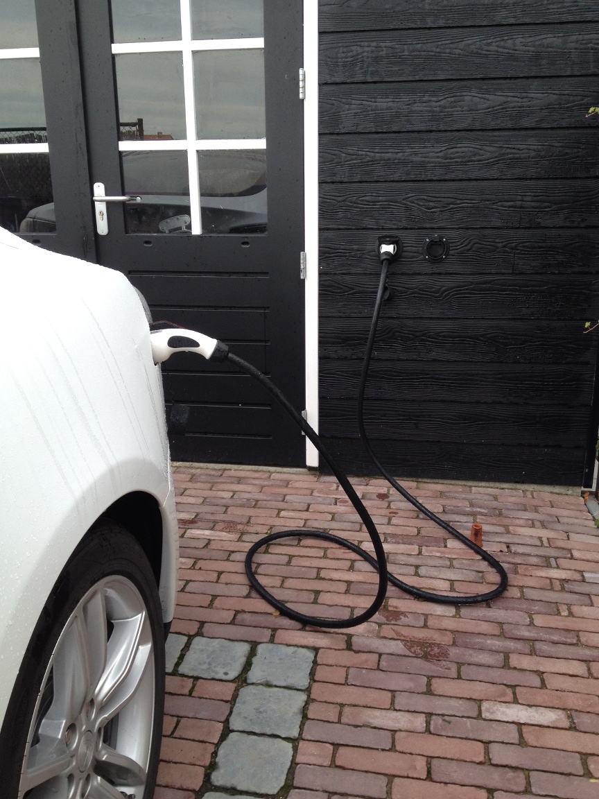
Hier is te zien dat er slechts twee contactpunten zijn, de kabel in het laadstation (in de muur verwerkt) en de aansluiting in de auto.

Dit is echter niet alles, een laadstation heeft een aantal extra veiligheden ten opzichte van een Rode CEE aansluiting:

  • Vergrendeling tijdens het laden. Het is onmogelijk om de kabel uit de auto en/of het laadstation te halen terwijl de auto aan het laden is.
  • Een Type 2 kabel heeft 7 pinnen waar een CEE 5 pinnen heeft. Over deze 2 extra pinnen vindt communicatie plaats alvorens het laadstation vermogen levert aan de auto.
  • De Type 2 aansluitingen zijn ontwikkeld om in de elementen gebruikt te worden. Zo hebben de aansluiting gaten voor water afvoer indien ze in de regen gebruikt worden.

7 vs 5 pinnen
Een Type 2 aansluiting heeft 7 pinnen waar een CEE 5 pinnen heeft. Allereerst hebben ze het volgende gemeen:

  1. GND: Een pin voor aarde.
  2. N: Een pin voor de neutraal.
  3. L1: Een pin voor fase 1.
  4. L2: Een pin voor fase 2.
  5. L3: Een pin voor fase 3.

Tot zo ver zijn de Type 2 aansluiting en de CEE aansluiting het zelfde. Een Type 2 aansluiting heeft echter nog een Control Pilot (CP) en Proximity Pilot (PP) pin.

De CP en PP pinnen worden gebruikt voor communicatie tussen het laadstation en de auto. Via deze pinnen wisselen het laadstation en de auto informatie uit over het beschikbare vermogen en doen een controle van de kabel. Indien aan alle voorwaarden voldaan is schakelt het laadstation een relais in waarna de spanning richting de auto gaat.

Zodra het laden begint zal het laadstation de kabel vergrendelen en aan de zijde van de auto gebeurd het zelfde. Hierdoor is het dus onmogelijk om de kabel uit de auto of het laadstation te halen terwijl er 11 of 22kW (de Model S kan tot 22kW laden bij een Type 2 laadstation) richting de auto gaat.

Een Type 2 connector is echter wel op alle scenario’s ontworpen en dat is goed te zien:

Type 2 Connector Pins

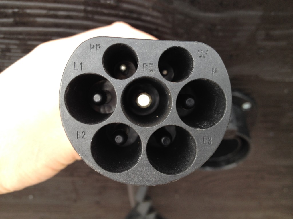
Als je goed kijkt naar de pinnen zie je dat deze qua lengte verschillen, in volgorde van lang naar kort:

  1. GND
  2. Neutral
  3. Proximity Pilot (PP)
  4. L1, L2 en L3
  5. Control Pilot (CP)

Het laden kan enkel geschieden wanneer zowel de CP als de PP verbonden zijn.

Mocht het vergrendelen van de kabel door bijvoorbeeld een defect mechanisme falen en de kabel wordt toch uit de aansluiting gehaald tijdens het laden, dan zal als eerste de Control Pilot zijn connectie verliezen. Dit is immers de kortste pin.

Zodra echter de CP niet meer verbonden is zullen de auto en het laadstation per direct het laadproces stoppen. Nog voordat de overige pinnen geen contact meer maken is de gehele aansluiting spanningsloos en zal er dus geen slijtage optreden omdat er simpelweg geen vermogen meer door de aansluiting gaat.

Door deze veiligheden is een Type 2 laadstation dus significant veiliger dan laden via een Rode CEE aansluiting..

Andere motivaties voor een Type 2 laadstation

Niet alleen veiligheid speelt een rol, maar naar mijn mening spelen ook de volgende redenen nog een rol:

  • Gemak
  • Toekomst bestending
  • Mogelijkheid tot Smart Charging

Gemak omdat iedereen hier mee overweg kan. Willen we dat elke ‘idioot’ een elektrische auto kan rijden, dan moet de vraag over welke aansluiting te gebruiken helemaal niet bestaan. De toekomstige EV rijders zullen niet allemaal even begaan zijn met elektriciteit en moeten enkel weten dat ze de Type 2 kabel gewoon in de auto en het laadstation moeten aansluiten waarna de rest vanzelf gebeurd.

Toekomst bestending omdat elke EV bij een Type 2 laadstation kan opladen. Wanneer we overal verschillende aansluitingen hebben moet je rond rijden met een berg aan verloopkabels en adapters, want je weet nooit wat je van te voren tegen gaat komen. Dit argument gaat ook op bij een aansluiting thuis. Over een paar jaar kan je best bezoek krijgen die ook met een EV langs komt. Moeten zij dan van te voren vragen welke verloopstukken ze mee moeten nemen? Als ze weten dat jij een EV thuis hebt zouden ze er toch vanuit mogen gaan dat het gewoon een Type 2 aansluiting is?

En wat als je over 5 jaar een nieuwe EV koopt? Moeten daar dan ook weer allemaal aparte kabels bij om die te kunnen opladen? Het is wel zo handig als deze gewoon in een Type 2 laadstation kan inprikken en kan laden.

Smart Charging is het laatste argument wat een extra motivatie kan zijn. Doordat het laden met een Type 2 laadstation intelligent gaat kan tijdens het laden het vermogen naar beneden en naar boven worden aangepast. Door het laadstation te koppelen met een slimme energie meter kan het laadvermogen worden afgestemd op het actuele verbruik in huis.

Wordt bijvoorbeeld de oven aan gezet dan kan het zijn dat de auto tijdelijk even minder vermogen mag afnemen om zo te voorkomen dat de hoofdzekeringen er uit springen. Iets wat onmogelijk is met dom laden via een CEE aansluiting.

Dit maakt het laden ook nog meer toekomst bestendig omdat zo elke ‘idioot’ overweg kan met een EV. We hoeven niet allemaal verstand te hebben van hoe het werkt. Gemak is ook belangrijk.

Samenvatting

Om dit allemaal nog even samen te vatten in een korte opsomming:

  1. Laden via een CEE aansluiting is niet veilig door het volledig ontbreken van veiligheids mechanismes.
  2. Een CEE aansluiting staat altijd onder spanning waar een Type 2 socket pas onder spanning komt te staan zodra een auto verbonden is en alle controles gedaan zijn.
  3. Het laden via een CEE is niet gemakkelijk doordat er rekening moet worden gehouden met verloopstukjes en adapters.
  4. Een Type 2 station is toekomst bestendig omdat elke elektrische auto hier probleemloos kan opladen.
  5. Smart Charging is enkel mogelijk met een Type 2 laadstation en onmogelijk met een CEE aansluiting.

Een 11kW laadstation installeren kost eenmalig tussen de EUR 1000,00 en 2000,00 afhankelijk van het werk wat verricht moet worden, maar daarmee ben je wel volledig toekomst bestendig.

Mijn advies is dan ook om een Type 2 laadstation thuis (of waar dan ook) te installeren en de UMC enkel in noodgevallen te gebruiken waar een Type 2 station niet beschikbaar is.

Ik durf het dan nog beter te stellen: Tesla had bij de Model S nooit een UMC gratis moeten leveren. In plaats van de UMC hadden ze gratis een Type 2 kabel moeten leveren en EUR 500,00 moeten rekenen voor een UMC.

De Tesla UMC en de Rode CEE aansluitingen komt de adoptie van elektrisch rijden niet ten goede.

Welk laadstation te kiezen?

Overtuigd dat een Type 2 laadstation toch beter is? Welke dan te kiezen?

Ik heb mijn laadstation thuis zelf gemaakt, dus ik heb niet al te veel ervaring met de commerciële producten, maar als ik een aanbeveling mag doen, kies dan voor:

Elke fabrikant heeft zijn voor en nadelen waar ik verder geen mening over ga hebben. Zolang er maar wordt gekozen voor een Type 2 station wordt het laden veiliger en gemakkelijker.

How I built my 3-phase Open EVSE

Ever since I posted on my blog that I built my own Open EVSE for my future Tesla Model S I’m getting a lot of e-mails from people asking how I build it.

A couple of notes to everybody who wants to build one:

I’m using a Open EVSE board with a modified firmware
I modified the firmware so that with the Advanced Power Supply it will switch to level 2 charging when it senses 230V on L1.

The source code can be found on my Github account.

I also have two compiled versions (with LCD support) available (both from 01-09-2012):

You can program the EVSE using ‘avrdude’ and the right programmer.

The relais I’m using is a 40A 4p
I’m using a Hager ESL440S relais.

This relais has 4 poles and works on 12V AC or DC.

There is a second relais which switches on my main relais
The main relais (Hager ESL440S) works on 12V DC, but pulls about 1000mA to switch on.

That is a bit to much for the Open EVSE board, so I had to buy a 12V DC transformer and a second smaller relais. When Open EVSE board switches on the small relais, it switches on the main relais by using the external 12V transformer.

If you go to page 8 of the PDF I wrote you can see these components.

In the casing where the Open EVSE board is you can see the small relais on the left.

The external 12V DC power supply is in the distribution panel on the right and is on the left of the main relais. You can see the green and red LED on it.

I limited my EVSE to 30A
I limited the pilot signal to 30A. 32A would stress some fuses in the distribution panel in my house, since that 32A relais also provides power to the TL-lights in my shed. So I turned the EVSE down to 30A instead of 32A. Technically I could use 32A, but 30A was a safe bet in this case.

1-phase of 3-phase doesn’t matter
The EVSE itself doesn’t know anything about 1-phase or 3-phase. When a car connects and talks to the EVSE it requests power, when all the criteria match the EVSE turns on the relais.

The car then senses 3-phases and will use them if the charger supports it. The EVSE has nothing to do with that.

To conclude:

  • Read the PDF I wrote.
  • For the EVSE 3-phase or 1-phase doesn’t matter. It just switches on a relais.
  • Read the Open EVSE website about J1772, programming, etc, etc

My EVSE is online!

It took some work and tuning, but my own Open EVSE is online!

After connecting the Advanced Power Supply cabling it’s automatically switchting to Level 2 charging on 30A.

I made a small change to the Open EVSE code since in the EU we have 230/400V instead of 110/220V. This can be found on my Github account.


Today I already got another Roadster on visit while helping him with installing OVMS in his 2.0 Roadster Sport. It charged nicely on 30A for about 4 hours.

To get Open EVSE working with the Roadster I had to add a 2.4k resistor on top of R1 to get the resistance back to 650 ~ 700 Ohm, like mentioned in the Open EVSE issue tracker.


Below are two pictures of both Roadster charging at the newly installed EVSE.

If you have any questions, feel free to contact me!

Installing the socket of my Open EVSE

While the shed in my backyard is still under constructing I started installing the Type 2 socket on the outer wall on the side of my parking spot.

For my EVSE I’m using the Open EVSE project. Although we use a different connector in Europe, the signaling is the same as with the J1772 connector. One other advantage is that the European connector has support for 3-phase power.

My shed has a outer and inner wall with the main supports in between them, I’m trying to run most cabling inside the wall for the aesthetics. For the socket it was also the easiest way.

A couple of pictures of what I did so far (still took me 5 hours though! Those stiff cables don’t make it any easier!).


This is the Type 2 socket for installation in a wall. This picture is without the interlocking actuator. The actuator is used for locking the connector in the socket while charging. It’s to prevent you from taking out a connector which might be carrying 22kW of power, that would give some fireworks!


This is the socket with the actuator installed on top of it. It’s a very simple 12V motor which pushes a pin into the socket and locking the connector in place.

I haven’t found a way yet to control this with the Open EVSE project, but I’m positive I’ll find a way to do so.

Locking is done by putting 12V on it for 300ms and unlocking is done by simply reversing the poles. Any suggestions how to do this with Open EVSE are welcome!


This now had to be installed in the outer wall of my shed. This wall is 11mm thick while the connector is build for 9mm at max. It took some power tools to get about 4mm off that wall!


This is how it looks on the outer wall after installation. You can see the actual socket still lying there, but the outer cap has been installed.

The socket itself is very well build by Mennekes. Rubbers everywhere to prevent water from coming in, but it also has water drainage output on the bottom. Should somebody plug in a connector full of water the excess water can flow out of the socket.

It’s a pretty expensive socket (EUR 300,00) but they did their job of creating a descent one!


This picture shows the installed socket from the back with the main power lines connected.

WARNING: These cables are NOT energized! The power flow is controlled by the EVSE with a relais. Take note of that should you consider installing your own EVSE!

The PP (Proximity Pilot) and CP (Control Pilot) pins are not connected yet, you however see the CAT6 cable already there. I’m using that cable for the CP and PP pins as well as for controlling the actuator.

The power cable is a 5G6 cable. This means 5 wires of 6mm2 each. My goal is to have this EVSE installation be able to deliver 3-phase 32A (22kW). 4mm2 cabling would maybe have done the job, but safety first! It also means less voltage drop, so more kW to the car!

The flexible PVC hose at the bottom is water drainage from the socket, should water enter the socket it can flow out of the socket through there.


This is how it all looks after installation with the actuator installed.

One PVC pipe carries the the main power cable while the other carries the CAT6 cable for controlling the actuator and connecting the PP and CP pin.

The pipes run through the structure towards the main power panel (yet to be installed) where I’ll also install the Open EVSE.

Between the outer and inner wall there will be insulation, but I have to prevent this from making contact with the socket. I still have build something for that around the socket, I want to make sure the insulation doesn’t catch fire for some reason. (Although I don’t know if it actually burns).

It’s better to be safe then sorry in this case. 22kW of power will flow through here, that is something not to be taken lightly, that is some serious amount of power!


If you want to order this socket yourself contact EV-Box (Netherlands), they can help you with that.

These are the parts I ordered (Mennekes part numbers):

  • 30012: Fixing ring with hinged lid IP44
  • 31016: Type 2 socket 32A with actuator
  • 30019: Actuator connector with 3 wires of 1m each

When I finish my EVSE I’ll post a full list of components I used.

Now it’s back to my shed for doing some more installation of other electronics like lighting.

Building my own EVSE


While I’m waiting for my Tesla Model S I also bought a new house. In December 6th 2011 I received the keys and ever since I’ve been working on the electrical infrastructure to prepare everything for the 3-phase charging station (EVSE) which should go into the garage.

I modified my fistribution panel to have a dedicated 3x32A connection to my garage where I can install my EVSE. The purpose is not only to charge the future Model S, but also the Roadster of my colleague and other EV’s which might visit me.

But then, which EVSE do you buy? I’ve been looking around and a EVSE capable of 3x32A costs about EUR 2000,00! It’s nothing more then a CFGI, a fuse and a controller, so I figured that could be done for less.

After some searching I found the Open EVSE project. I was sold right away! What’s cooler then building your own EVSE with Open Source software!?

I ordered the Open EVSE kit with the Advanced Power Supply and got it last week. Right now I’m waiting for my 63A relais (I like it beefy) and some other components like the Type 2 socket for in the outer-wall of my garage.


The Model S won’t fit in the garage, so I’m going to install the Type 2 socket in the outer-wall of the garage. All the EVSE components can be inside, that will make it very clean. Just a Type 2 socket where you plug in your EV and it starts charging! Couldn’t be easier.


To my garage I’m running a 5G6 cable. That’s five wires of 6mm2 each. This cable will be capable of doing 3x32A which should recharge the 85kWh battery in a little bit over 4 hours.

My main fuses are 40A, so when I’m charging with 3x32A I can’t turn on my oven or use my electrical cooking. Open EVSE however supports dynamically changing the current.

In my distribution panel I have a kWh meter with a M-Bus exit over which I can read out the current going through my main fuses. I’ve made a nice web page where I display this information, but the main goal is to have the EVSE read out this data and adjust the current based on what other appliances in my house are using.

This way I’ll never blow my main fuses and I’ll still be able to use 32A at the EVSE when available. Something like my little smart grid!

As I’m still waiting for a couple of components I’m not going to post anything yet about which I’m using. I promise, I’ll add a Wiki on the Open EVSE page about how I build my 3-phase EVSE with Open EVSE!

That’s it for now, keep tuned for more information!

Now it’s back to waiting… Not only for the components, but also for the Model S!

The Model S will support 3-phase charging!

I’ve wrote a letter to Tesla, wrote a blogpost about it and discussed it on the Tesla Motors Club forum and it seems it has paid off!

Tesla Motors just announced that the Model S will support 3-phase charging in Europe!

On Twitter they tweeted:

Tesla’s Model S in Europe will be capable of three phase charging.

That is great news for all future Model S owners in Europe!

Now it’s back again to waiting for the Model S to be parked at my house.

3-phase and CHAdeMO charging for the Model S?

The biggest issue with Electric Vehicles (EV’s) is charging. How do I charge my car within a reasonable time frame? Charging within 1 hour is possible, but you need a lot of power to do so. That is not available on all locations and requires special chargers.

Almost two years ago I made a reservation for a Tesla Model S, the car which I think is the best EV to come to the market.

In the summer of 2011 I was invited to a ‘reservation holder only event‘ at the Tesla factory in Fremont California. I went there and saw the Model S for the first time: Wow…. I was blown away, what a beauty.

EV’s however are new and not everything is technically the way you want it to be.

What is 3-phase charging and why would you want it?

Timely charging is the biggest issue with EV’s. With 3-phase charging you could charge your EV 3 times faster, since Europe has a 3-phase power grid.

I live in Europe (The Netherlands) and  unlike the USA were are limited to ~32A per phase. In the USA you can get a 100 Amp installation in your house. Amps and Volts is all that counts when you want to charge an EV.

With a 100 Amp connection in the USA, you get 20kW of power. (100A * 208V =~ 20kW). The biggest battery of a Model S is 85kWh (Kilowatt hour). 85 kWh / 20kW = 4.25 hour of charging (not taking any losses into account).

Like mentioned, in Europe we have a 3-phase power grid and we are limited to 32A per phase in residential areas (Rules are complex!). 32A at 230V = 7.3kW.

The 85kWh battery of a Model S would take almost 12 hours (85 / 7.3) to charge.

Here comes the 3-phase power into play. We can get 3 times 32A in our hose at 400 Volts. (See the Wikipedia page). This calculation is a bit more complex: 400 * 32 * SQ(3) =~ 20kW. We also get 20kW of power in our residential areas, but it’s delivered to us spread out over 3-phases instead of one.

The bottom-line is: Without 3-phase charging it will take three times longer to charge a Model S in Europe then in the USA. That’s why I want 3-phase charging for the Model S.

When I made my reservation the Tesla website stated that the Model S could charge from 110V, 220V and 480V. From that moment I assumed the Model S would support 3-phase charging, but then I went to the event at the factory in Fremont.


This picture shows the new charging connector of the Model S. Tesla designed a new connector which could handle AC (low to medium (20kW)) power and DC (high >50kW)) power over the same pin layout. This results in a very sleek connector. A great connector if you look at it from a designers perspective.

The connector is however lacking a 2nd and 3rd connector for 3-phase charging. This connector design only has:

  • A ground (bottom middle)
  • A proximity and pilot connection (bottom left and right)
  • A Phase connection (top left or right)
  • A neutral connection (top left or right)

In order to support 3-phase power the connector should have two more ‘big’ connectors.

I asked a Tesla employee if the Model S could charge from 3-phases and he said “No, it won’t” I felt really disappointed. I had been waiting on the Model S for such a long time already (18 months), living with the assumption (since the website stated 480V charging) that it would support 3-phase charging.


The employee told me that Tesla focused on Quick/Fast/Super-charging a Model S with high power DC (500V, ~200A, 90kW, 45 min) instead of the slower charging. The Model S would also be able to travel such long distances that you could do almost all your driving without charging. I argued he was wrong, but it was quite busy at the event, so I didn’t get into a in-depth discussion with him.

Although the event at the Tesla factory was great, the news about the lack of 3-phase charging gave a real bad taste.

In the car back to the hotel I started brainstorming with my colleague (the Roadster owner) about how we could convince Tesla otherwise. As a Roadster owner in Europe he’s also quite disappointed about the Roadsters limitation to 7kW (32A @ 230V) charging (8 hours) in Europe. He however accepted it since the Roadster is a car for pioneers, early adopters or tech freaks, however you want to call them.

If you by a base Model S you get one on-board 10kW AC charger, but if you pay $1500,00 you get a second 10kW charger which runs parallel with the first charger, giving you 20kW AC charging.

Wait a minute? 20kW AC charging? That is exactly what we want in Europe! In the US the chargers run parallel on 1-phase, as Europeans we want the 20kW spread out over 3-phases. So what is the point? Tesla clearly sees that 20kW AC charging is useful in the US, why not in Europe?

To get back to the brainstorming: We came up with the idea to write a letter to Tesla and start collection signatures from people who agreed with me. So I did, I wrote a letter to Tesla together with 39 hand written signatures.

On the right two pictures of how this looked.

On November 4th 2011 I sent this package to the Tesla HQ in Palo Alto, CA, USA and I started waiting…


After a month of waiting for just a “Thank you for your letter” I also sent the letter to the Tesla EU HQ in London and posted a Tweet. That is when I got a “Thank you” from Tesla, but nothing conclusive. I never expected Tesla to reply within a month with a answer that they would or wouldn’t support 3-phase charging.

I completely understand that such decisions might have a big impact and involve a lot of people, so these kind of things take time.

However, is implementing 3-phase support that hard? I think it’s not. The biggest obstacle I think is the connector (see above) that Tesla designed. It’s missing the necessary connections for L2 (2nd phase) and L3 (3rd phase), so they would have to redesign that connector. They could also add a second charging port on the car and support the IEC 62192-2-2 connector natively without any adapters?


3-phase charging would drastically improve the usage of the Model S. On a 3x16A (10kW) connection you could charge a Model S with it’s 85kWh battery in about 8 hours. A Nissan Leaf also charges in 8 hours, but a full charge of a Leaf gets you 160km, a full Model S takes you up to 480km.

A 3x32A connection (20kW) could charge a Model S in a bit over 4 hours.

I made a graph to display the various charging times for a Model S and a Roadster. You get the picture why 3-phase charging is really needed for the Model S!


Without 3-phase charging you wouldn’t even be able to charge your Model S overnight! How are you supposed to charge the Model S if you get back home later in the evening and want to leave the next morning? A full charge could take over 24 hours!

Most (bigger) hotels in Europe also have a 3-phase connection available somewhere in the parking lot, if not, it is trivial to get such a connection installed. With just a single-phase socket you can’t charge your Model S overnight (see the chart above).

That is why I emphasized this to Tesla: “European’s don’t want 3-phase charging, they need 3-phase charging!”

The faster you can charge your EV, the better. It makes the car more practical, simple as that.

The final decision is at Tesla, but I think that supporting 3-phase charging is trivial and vital for Tesla if they want to be successful in Europe. In my letter to Tesla I showed them how many 3-phase charging stations are available in Europe. The current estimate is that over 2.500 (~1300 in Holland alone!) of these charging stations are installed in Northern Europe and they are being installed on a daily basis. (Amsterdam is installing at least one every week).

We just saw the release of the Pricing & Options of the US Model S, so I’m not expecting a answer from Tesla really soon. I however have good hope that Tesla will implement 3-phase charging for the Model S. My hope is that they will reveal it at the Geneva Motor Show in March 2012.


Something else which has been bothering me is the DC (fast-charging) charging Tesla will be using for the Model S. They say it will be DC charging at 500V and can top up your Model S in 45 minutes. They call it “Supercharging”.

Around the world (especially in Europe and Japan) fast-chargers are being installed which are compliant to the CHAdeMO protocol.

CHAdeMO is a fast-charge protocol which delivers up to 50kW of power. If we take a look again at the calculations above: 85kWh / 50kW = 1.7 hours for a full charge.

The Nissan Leaf is one of the first cars to support CHAdeMO fast-charging. A CHAdeMO station can recharge the 24kWh battery of a Leaf in 30 minutes.

Yes, the 50kW a CHAdeMO charger delivers is 60% of the 90kW Tesla is intending to use, but still, 50kW is better then nothing.

Tesla claims that they will be installing their “Super chargers” throughout the US and even Europe, concrete plans are however lacking.

The CHAdeMO chargers are being rolled out today. Nissan recently said that they will donate 400 chargers in Europe. 400 chargers!? That is great! If the Model S could take advantage of these chargers you could travel even further.

CHAdeMO seems to be winning in Europe and Japan as it comes to fast-charging. I’m not sure about the US, but it seems it’s getting traction there as well. In 2012 there will be hundreds or more then a thousand of these chargers throughout Europe. It would be a shame if the Model S can’t charge there.

BP (British Petroleum) has started installing CHAdeMO chargers at their stations along highways in the Netherlands, but incentives like those are being initiated all over Europe. In 2011 the Norwegian energy company Ishasvkraft announced that they will be installing CHAdeMO chargers throughout Norway. Lysi Energy is doing the same in Norway.

On the Tesla Motors Club forum I recently started a thread on CHAdeMO charging for the Model S. We can be almost a 100% sure that the Model S won’t natively support CHAdeMO charging, but there is always the possibility of an adapter. Tesla did not reveal any plans for such an adapter, but there is hope.


My message to Tesla is that they should make the Model S the best EV on the planet and crush all competition. I’m blown away by the Model S and can’t wait to receive mine. It would however be a shame if the car would be limiting me by not letting me take advantage of the available power provided by 3-phase and CHAdeMO charging stations.

The specifications of the Model S are great, no doubt about that. Just make sure that I as a driver can take full advantage of all the charging possibilities which are available. That would make me (and I think a lot with me) a very, very, very happy customer!