How I built my 3-phase Open EVSE

Ever since I posted on my blog that I built my own Open EVSE for my future Tesla Model S I’m getting a lot of e-mails from people asking how I build it.

A couple of notes to everybody who wants to build one:

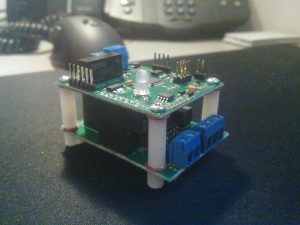
I’m using a Open EVSE board with a modified firmware
I modified the firmware so that with the Advanced Power Supply it will switch to level 2 charging when it senses 230V on L1.

The source code can be found on my Github account.

I also have two compiled versions (with LCD support) available (both from 01-09-2012):

You can program the EVSE using ‘avrdude’ and the right programmer.

The relais I’m using is a 40A 4p
I’m using a Hager ESL440S relais.

This relais has 4 poles and works on 12V AC or DC.

There is a second relais which switches on my main relais
The main relais (Hager ESL440S) works on 12V DC, but pulls about 1000mA to switch on.

That is a bit to much for the Open EVSE board, so I had to buy a 12V DC transformer and a second smaller relais. When Open EVSE board switches on the small relais, it switches on the main relais by using the external 12V transformer.

If you go to page 8 of the PDF I wrote you can see these components.

In the casing where the Open EVSE board is you can see the small relais on the left.

The external 12V DC power supply is in the distribution panel on the right and is on the left of the main relais. You can see the green and red LED on it.

I limited my EVSE to 30A
I limited the pilot signal to 30A. 32A would stress some fuses in the distribution panel in my house, since that 32A relais also provides power to the TL-lights in my shed. So I turned the EVSE down to 30A instead of 32A. Technically I could use 32A, but 30A was a safe bet in this case.

1-phase of 3-phase doesn’t matter
The EVSE itself doesn’t know anything about 1-phase or 3-phase. When a car connects and talks to the EVSE it requests power, when all the criteria match the EVSE turns on the relais.

The car then senses 3-phases and will use them if the charger supports it. The EVSE has nothing to do with that.

To conclude:

  • Read the PDF I wrote.
  • For the EVSE 3-phase or 1-phase doesn’t matter. It just switches on a relais.
  • Read the Open EVSE website about J1772, programming, etc, etc

My EVSE is online!

It took some work and tuning, but my own Open EVSE is online!

After connecting the Advanced Power Supply cabling it’s automatically switchting to Level 2 charging on 30A.

I made a small change to the Open EVSE code since in the EU we have 230/400V instead of 110/220V. This can be found on my Github account.


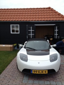
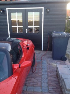
Today I already got another Roadster on visit while helping him with installing OVMS in his 2.0 Roadster Sport. It charged nicely on 30A for about 4 hours.

To get Open EVSE working with the Roadster I had to add a 2.4k resistor on top of R1 to get the resistance back to 650 ~ 700 Ohm, like mentioned in the Open EVSE issue tracker.


Below are two pictures of both Roadster charging at the newly installed EVSE.

If you have any questions, feel free to contact me!

Installing the socket of my Open EVSE

While the shed in my backyard is still under constructing I started installing the Type 2 socket on the outer wall on the side of my parking spot.

For my EVSE I’m using the Open EVSE project. Although we use a different connector in Europe, the signaling is the same as with the J1772 connector. One other advantage is that the European connector has support for 3-phase power.

My shed has a outer and inner wall with the main supports in between them, I’m trying to run most cabling inside the wall for the aesthetics. For the socket it was also the easiest way.

A couple of pictures of what I did so far (still took me 5 hours though! Those stiff cables don’t make it any easier!).
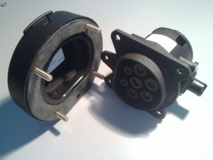


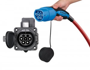
This is the Type 2 socket for installation in a wall. This picture is without the interlocking actuator. The actuator is used for locking the connector in the socket while charging. It’s to prevent you from taking out a connector which might be carrying 22kW of power, that would give some fireworks!
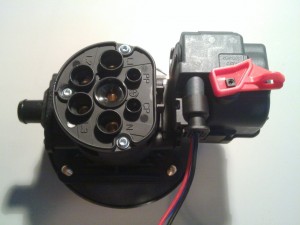


This is the socket with the actuator installed on top of it. It’s a very simple 12V motor which pushes a pin into the socket and locking the connector in place.

I haven’t found a way yet to control this with the Open EVSE project, but I’m positive I’ll find a way to do so.

Locking is done by putting 12V on it for 300ms and unlocking is done by simply reversing the poles. Any suggestions how to do this with Open EVSE are welcome!


This now had to be installed in the outer wall of my shed. This wall is 11mm thick while the connector is build for 9mm at max. It took some power tools to get about 4mm off that wall!
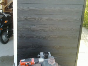


This is how it looks on the outer wall after installation. You can see the actual socket still lying there, but the outer cap has been installed.

The socket itself is very well build by Mennekes. Rubbers everywhere to prevent water from coming in, but it also has water drainage output on the bottom. Should somebody plug in a connector full of water the excess water can flow out of the socket.

It’s a pretty expensive socket (EUR 300,00) but they did their job of creating a descent one!
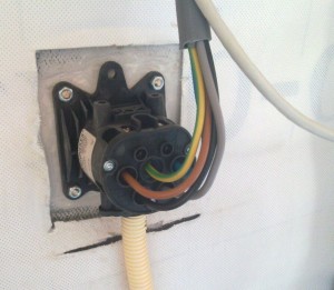


This picture shows the installed socket from the back with the main power lines connected.

WARNING: These cables are NOT energized! The power flow is controlled by the EVSE with a relais. Take note of that should you consider installing your own EVSE!

The PP (Proximity Pilot) and CP (Control Pilot) pins are not connected yet, you however see the CAT6 cable already there. I’m using that cable for the CP and PP pins as well as for controlling the actuator.

The power cable is a 5G6 cable. This means 5 wires of 6mm2 each. My goal is to have this EVSE installation be able to deliver 3-phase 32A (22kW). 4mm2 cabling would maybe have done the job, but safety first! It also means less voltage drop, so more kW to the car!

The flexible PVC hose at the bottom is water drainage from the socket, should water enter the socket it can flow out of the socket through there.
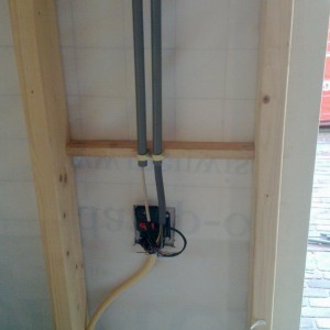


This is how it all looks after installation with the actuator installed.

One PVC pipe carries the the main power cable while the other carries the CAT6 cable for controlling the actuator and connecting the PP and CP pin.

The pipes run through the structure towards the main power panel (yet to be installed) where I’ll also install the Open EVSE.

Between the outer and inner wall there will be insulation, but I have to prevent this from making contact with the socket. I still have build something for that around the socket, I want to make sure the insulation doesn’t catch fire for some reason. (Although I don’t know if it actually burns).

It’s better to be safe then sorry in this case. 22kW of power will flow through here, that is something not to be taken lightly, that is some serious amount of power!


If you want to order this socket yourself contact EV-Box (Netherlands), they can help you with that.

These are the parts I ordered (Mennekes part numbers):

  • 30012: Fixing ring with hinged lid IP44
  • 31016: Type 2 socket 32A with actuator
  • 30019: Actuator connector with 3 wires of 1m each

When I finish my EVSE I’ll post a full list of components I used.

Now it’s back to my shed for doing some more installation of other electronics like lighting.
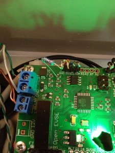
Building my own EVSE


While I’m waiting for my Tesla Model S I also bought a new house. In December 6th 2011 I received the keys and ever since I’ve been working on the electrical infrastructure to prepare everything for the 3-phase charging station (EVSE) which should go into the garage.

I modified my fistribution panel to have a dedicated 3x32A connection to my garage where I can install my EVSE. The purpose is not only to charge the future Model S, but also the Roadster of my colleague and other EV’s which might visit me.

But then, which EVSE do you buy? I’ve been looking around and a EVSE capable of 3x32A costs about EUR 2000,00! It’s nothing more then a CFGI, a fuse and a controller, so I figured that could be done for less.

After some searching I found the Open EVSE project. I was sold right away! What’s cooler then building your own EVSE with Open Source software!?

I ordered the Open EVSE kit with the Advanced Power Supply and got it last week. Right now I’m waiting for my 63A relais (I like it beefy) and some other components like the Type 2 socket for in the outer-wall of my garage.


The Model S won’t fit in the garage, so I’m going to install the Type 2 socket in the outer-wall of the garage. All the EVSE components can be inside, that will make it very clean. Just a Type 2 socket where you plug in your EV and it starts charging! Couldn’t be easier.


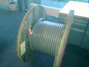
To my garage I’m running a 5G6 cable. That’s five wires of 6mm2 each. This cable will be capable of doing 3x32A which should recharge the 85kWh battery in a little bit over 4 hours.

My main fuses are 40A, so when I’m charging with 3x32A I can’t turn on my oven or use my electrical cooking. Open EVSE however supports dynamically changing the current.

In my distribution panel I have a kWh meter with a M-Bus exit over which I can read out the current going through my main fuses. I’ve made a nice web page where I display this information, but the main goal is to have the EVSE read out this data and adjust the current based on what other appliances in my house are using.

This way I’ll never blow my main fuses and I’ll still be able to use 32A at the EVSE when available. Something like my little smart grid!

As I’m still waiting for a couple of components I’m not going to post anything yet about which I’m using. I promise, I’ll add a Wiki on the Open EVSE page about how I build my 3-phase EVSE with Open EVSE!

That’s it for now, keep tuned for more information!

Now it’s back to waiting… Not only for the components, but also for the Model S!