Connect ISG Web to Stiebel Eltron WPL20AC heatpump

Our house (2020) is being heated and cooled by a Stiebel Eltron WPL20AC heatpump. Being a techy I searched if there was a possibility to extract some statistics out of the heat pump and connect it to my Home Assistant.
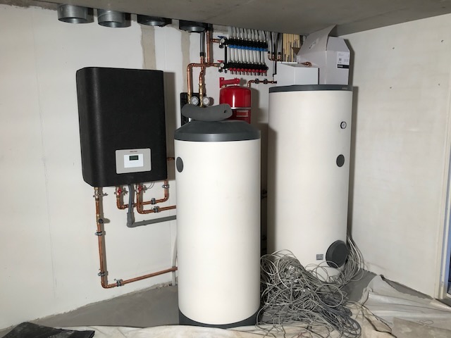
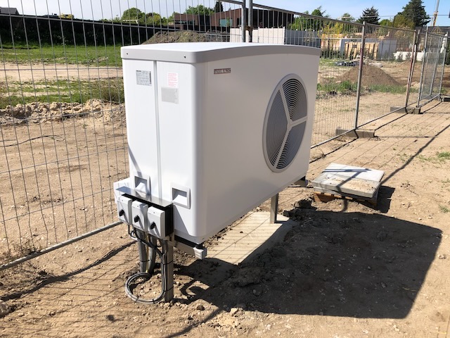
The pictures above show the system while being installed in the summer of 2020.

ISG web

Fast forward to 2024 and after some searching I found the ISG web from Stiebel Eltron.

A device which connects to the CAN bus of the heatpump and exposes the information via a Web UI and additionally via Modbus TCP/IP (additional software required!).

I purchased a ISG web (EUR 170) and tried to connect it myself.
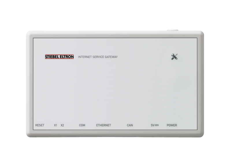
Stiebel Eltron ISG web

I thought it was a matter of connecting the Ethernet and then the CAN bus cable on the WPsystem board inside the heatpump. Turned out everything on the board was occupied and the manuals of Stiebel Eltron were not very clear.

CAN bus connection

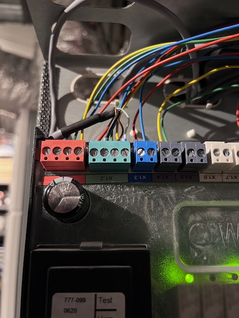
Luckily we had a servicemen come over for some maintenance on the heatpump and I asked him to connect the ISG to the WPsystem board. He did by connecting the cables to the GREEN (CAN B) connection X1.2.
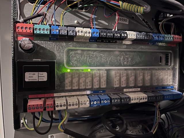
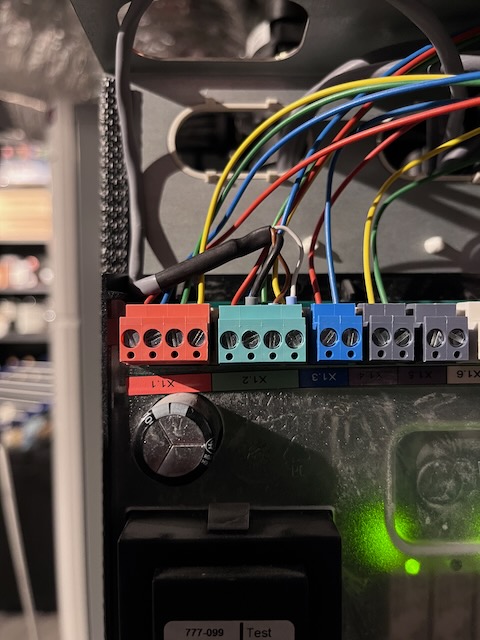
Here you can see the grey cable coming from the ISG web connected to the X1.2 connector in parallel.

ISG web UI

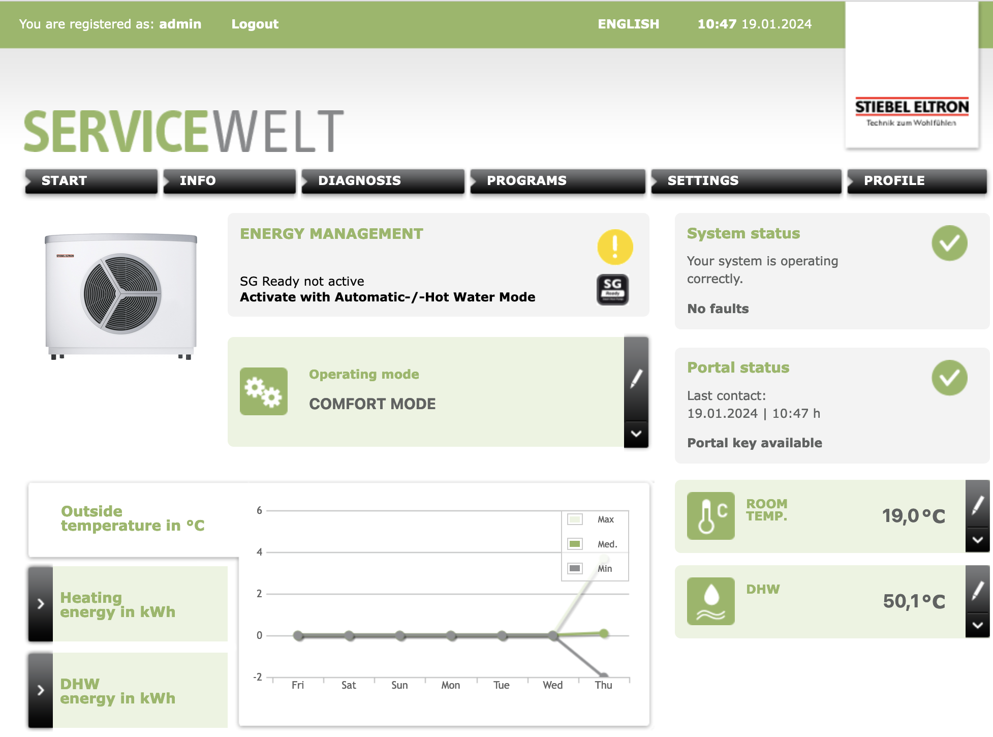
The ISG is now working and I can see the information in the Web UI.
Modbus & Home Assistant

On my todo list is to connect the ISG web to my Home Assistant using the Stiebel Eltron integration.

The Modbus TCP/IP port 502 doesn’t seem to respond on my ISG, but this might be due to the stock firmware 12.2.3 build 260 it was delivered with.

I have sent an e-mail to Stiebel Eltron asking them for advice to have Modbus enabled on my ISG. Once I know more I will update this post.

EVPN+BGP+VXLAN between JunOS and FRR (with Cumulus)

Recently I was asked to assist with setting up a BGP+EVPN+VXLAN network where Juniper MX204 routers would be the gateways in the VNI and the rest of the network would consist of Spine and Leaf switches running Cumulus Linux.

The actual workload would run on Proxmox servers which would also run Frrouting. I wrote a post about this earlier.

I’ll make this a short post as you are probably reading this to find a solution to your problem, I’ll make it short and post the configuration.

Interoperability

BGP and EVPN are standardised protocols and they should work between vendors. EVPN is however still fairly new and vendors sometimes implement features differently.

I noticed this with the route-targets/communities set by FRR and JunOS for EVPN routes. These would not match and thus JunOS and FRR would not learn eachothers EVPN routes.

Solution / Configuration

In this case the solution was to set the route-target/community/vrf-target for all EVPN routes (and thus VNI) to 100:100 (something I chose).

JunOS

wido@juniper-mx204> show configuration routing-instances evpn 
instance-type virtual-switch;
protocols {
    evpn {
        encapsulation vxlan;
        extended-vni-list all;
        multicast-mode ingress-replication;
    }
}
vtep-source-interface lo0.0;
bridge-domains {
    v1500 {
        vlan-id none;
        routing-interface irb.1500;
        vxlan {
            vni 1500;
            ingress-node-replication;
        }
    }
    v1501 {
        vlan-id none;
        routing-interface irb.1501;
        vxlan {
            vni 1501;
            ingress-node-replication;
        }
    }
}
route-distinguisher 10.255.0.1:100;
vrf-target target:100:100;

wido@juniper-mx204>

frrouting

router bgp 65118
 no bgp ebgp-requires-policy
 no bgp default ipv4-unicast
 no bgp network import-check
 neighbor upstream peer-group
 neighbor upstream remote-as external
 neighbor enp129s0f0np0 interface peer-group upstream
 neighbor enp129s0f1np1 interface peer-group upstream
 !
 address-family ipv4 unicast
  network 10.255.0.17/32
  neighbor upstream activate
 exit-address-family
 !
 address-family ipv6 unicast
  network 28xx:xxx::17/128
  neighbor upstream activate
 exit-address-family
 !
 address-family l2vpn evpn
  neighbor upstream activate
  advertise-all-vni
  vni 1500
   route-target import 100:100
   route-target export 100:100
  exit-vni
  vni 1499
   route-target import 100:100
   route-target export 100:100
  exit-vni
  vni 1498
   route-target import 100:100
   route-target export 100:100
  exit-vni
  advertise-svi-ip
 exit-address-family
exit

This now resulted in JunOS and Frr learning the EVPN routes and this then also showed in the EVPN database of JunOS. The VMs in Proxmox were now able to reach the internet!

wido@juniper-mx204> show evpn database l2-domain-id 1500 
Instance: evpn
VLAN  DomainId  MAC address        Active source                  Timestamp        IP address
     1500       00:00:5e:00:01:01  05:00:00:fd:e9:00:00:05:dc:00  May 22 06:57:59  xx.124.220.3
     1500       00:00:5e:00:02:01  05:00:00:fd:e9:00:00:05:dc:00  May 22 06:57:59  xx:xx:2::3
     1500       46:50:13:6d:5d:bb  10.255.0.17                    May 23 05:44:20
     1500       74:e7:98:30:8c:e0  irb.1500                       May 18 06:29:04  xx.124.220.1
                                                                                   xx:xx:2::1
                                                                                   fe80::76e7:9805:dc30:8ce0
     1500       80:db:17:eb:d5:d0  10.255.0.2                     May 22 06:57:59  xx.124.220.2
                                                                                   xx:xx:2::2
                                                                                   fe80::82db:1705:dceb:d5d0
     1500       9a:9a:94:80:1a:3a  10.255.0.17                    May 23 06:02:25
     1500       ca:f0:03:fe:d6:dd  10.255.0.17                    May 22 18:18:43
     1500       f6:db:10:b6:5b:c4  10.255.0.17                    May 23 05:58:39  xx.124.220.6

wido@juniper-mx204> 

Combined Charging System (CCS) and IPv6

When we talk about IP protocols and IPv6 in this particular case we think about routing over the internet. But what many do not know is that IPv6 is already playing a major role in all kinds of systems.

In this post I’m not going to explain IPv6 in detail, for many things I’ll link to external pages.

Ad-Hoc networking using Link-Local

IPv6 has a great feature where each host on a network will generate a Link Local Address (LL) which is mandatory according to the protocol.

The great thing about LL is that it allows hosts to establish communication without the need of DHCP or anything else. Just plug in a host on a Layer 2 Ethernet network and they can start communicating right away.

fe80::5054:ff:fe98:aaee is an example of a IPv6 LL address and using this address it can search for (via multicast) and communicate with other hosts in the network.

Examples of systems using IPv6 LL are Matter and Combined Charging System (CCS).

Combined Charging System (CCS)

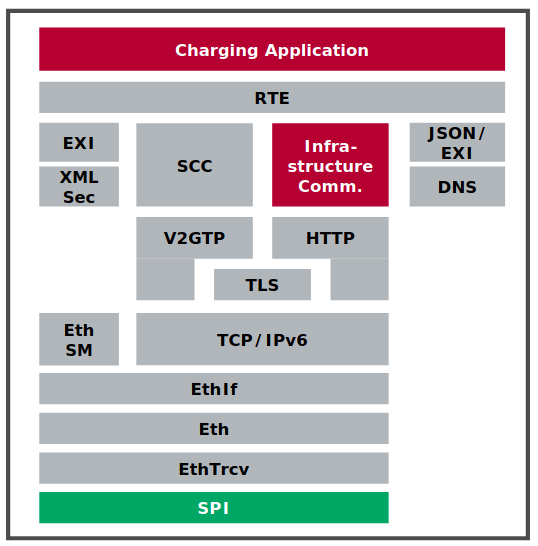
CCS is a standard for (fast charging) electric vehicles. Some years ago I stumbled upon multiple documents showing that CCS would be using a combination of PLC, IPv6, TCP/IP, UDP, HTTP, TLS and many other very common protocols for communication.

Using PowerLine Communication (PLC) the vehicle and charger will establish a Layer 2 Ethernet network over which they will communicate using IPv6 LL.

I was not able to find the exact details of the IPv6 part of the CCS standard, but it is very interesting to see that IPv6 is being used for something like charging electric vehicles.

Kudos to the people behind CCS and for using IPv6 for this!

In my opinion it’s a no-brainer to use IPv6 for such functionality as the LL addressing allow you to create networks very quickly and in a reliable manner.

You can also use a very well documented protocol and the many tools for IPv6.

Now I would like to run Wireshark on such a link!

If you have more information about this, please contact me!

Babycam using a Unifi G3 camera

It’s been almost a year that I’ve been living in my new house and proud father of a son.

Almost every parent wants to watch their little on through a camera to see them sleeping in their bed.

There are many, many, many baby monitors on the market but in my experience they are all crap. Our house is build with a lot of concrete and none of them was able to penetrate the walls in our house and thus have a reliable video connection.

I also tried some IP/WiFi based baby monitors from for example Foscam, but these are all cheap Chinese cameras and didn’t work either. Crashing iPad apps, sending random (UDP) packets to China, half-baked UIs, etc, etc. They were all very low quality.

After a lot of frustrating I bought a Unifi Video G3 (UVC-G3-BULLET) camera and mounted it on the bed of my son.

Unifi Video G3 camera mounted on baby bed

I am using multiple Unifi video cameras around my house using Unifi Video, so for me it was just a matter of adding an additional camera to my Unifi system.

Video camera in Unifi Video

RTMP + HLS with Nginx

I also experimented with building a video stream using RTMP, ffmpeg and HLS with Nginx.

The Unifi cameras can export a RTSP stream which you can set up to live stream with Nginx. I tried this and it works for me, but with a delay of ~20s I thought it was not usable on my use-case.

It does however allow for a very easy way of building your own webcam!

Linux mdadm software RAID vs Broadcom MegaRAID 9560

In the past years I’ve said goodbye to hardware RAID controllers and mainly relied on software solutions like mdadm, LVM, Ceph and ZFS(-on-Linux) for keeping data safe.

At PCextreme we use hypervisors with local NVMe storage running in Linux’s mdadm software RAID-10. This works great! But I wasn’t satisfied with the performance for a few reasons:

  • It is expensive on the CPUs (Dual AMD Epyc 48-core)
  • It’s not super fast

We mainly use the Samsumg PM983 (1.92TB) devices and I started to look around if there is a hardware solution which could offload the RAID computation to a dedicated SoC so it wouldn’t eat up our CPU cycles.

After searching I found the Broadcom SAS3916 chip which is on the MegaRAID 9516-16i controller from Broadcom. This chipset supports NVMe devices in various RAID modes.

I wanted to benchmark Linux’s software RAID against the Broadcom controller to see if it would be faster and save us the expensive CPU cycles.

With mdadm we also looked into RAID-5/6 to have more usable space. We however found out that this eats up so many CPU cycles that it wasn’t feasible to use in production for our purposes.

Benchmarking setup

  • Ubuntu Linux 18.04 with kernel 5.3
  • SuperMicro 1114S-WN10RT
  • AMD Epyc 7302P 16-core CPU
  • 128GB Memory
  • 4x Samsung PM983 1.92TB
  • Broadcom MegaRAID 9516-i

Benchmarking will be done using fio and the main elements we are looking for:

  • QD=1, 4, 8 and 16 4k random write performance
  • CPU utilization during benchmarks

MegaRAID configuration

The RAID-10 array was created using storcli

storcli64 /c0 add vd type=raid10 drives=252:4,6,8,10 pdperarray=2

mdadadm setup

RAID-10 was set-up using this command:

mdadm --create --level=10 --raid-devices=4 /dev/md0 /dev/nvme0n1 /dev/nvme1n1 /dev/nvme2n1 /dev/nvme3n1

fio

The fio jobs we ran to benchmark:

[global]
ioengine=libaio
direct=1
invalidate=1
bs=4k
runtime=300
filename=/var/lib/libvirt/images/fio
size=64g
rw=randwrite
numjobs=1

[rw_mdadm_1]
iodepth=1

[rw_mdadm_4]
iodepth=4

[rw_mdadm_8]
iodepth=8

[rw_mdadm_16]
iodepth=16

[rw_mdadm_32]
iodepth=32

Results

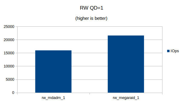
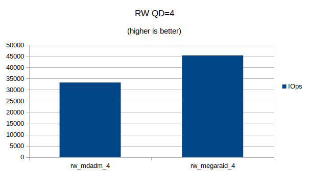
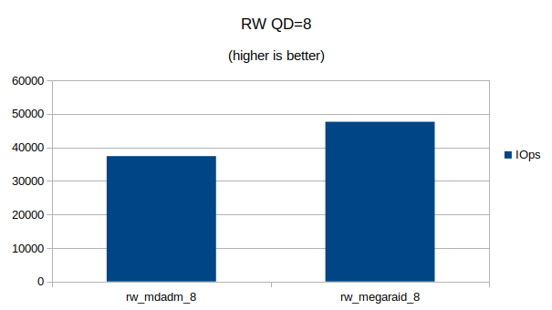
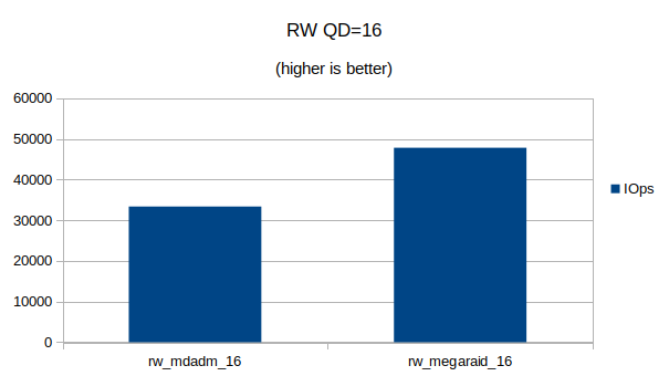
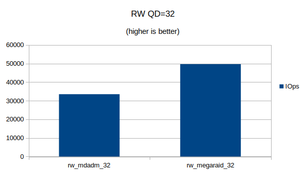
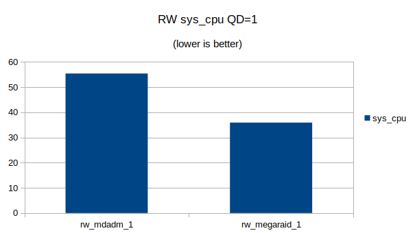
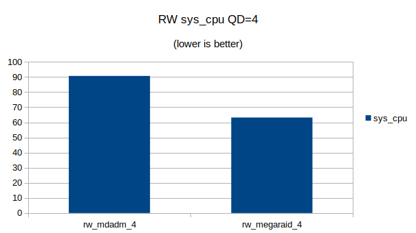
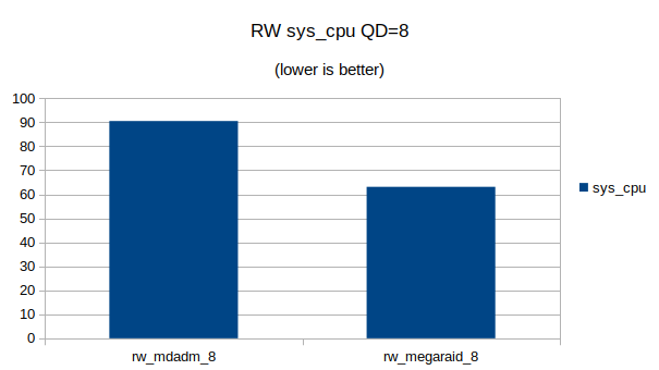
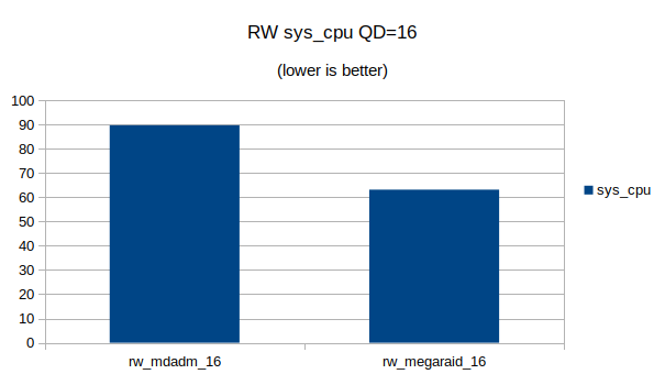
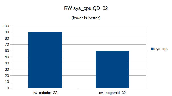
Short answer? The MegaRAID controller is much faster in RAID-10 mode and also saves up to 30% of CPU cycles on the Linux machine.

You can also download the JSON output from fio here:

In addition you can download my Open Office spreadsheet I used to generate the graphs and process the data.

Graphs

Some graphs with the results of the IOps and CPU utilization.

At QD 16~32 we seem to have found the upper limit of what the 4 NVMe devices are capable of. Going from QD 16 to 32 does not make a significant difference.
At QD32 we can still see that the MegaRAID controller uses a lot less CPU cycles then Linux’s software RAID

1Gbit fiber connection between MikroTik and Unifi switch

While replacing my router at home by a MikroTik CCR1036-8G-2S+ router I also wanted to uplink my Ubiquity switch using a Multimode (OM3) connection.

Is fiber really needed? Not really, but it saved me an additional RJ45 port on my switch which allows me to connect more.

Link up, down, up, down

The link between my MikroTik router and Unifi switch kept going up and down. In the logs on my MikroTik and Unifi switch I saw:

<14> May 26 19:19:07 SwitchPatchkast DOT1S[dot1s_task]: dot1s_sm.c(314) 454679 %% Port (26) inst(0) role changing from ROLE_DESIGNATED to ROLE_DISABLED
<14> May 26 19:19:07 SwitchPatchkast DOT1S[dot1s_task]: dot1s_sm.c(314) 454677 %% Port (26) inst(0) role changing from ROLE_DISABLED to ROLE_DESIGNATED
<13> May 26 19:19:07 SwitchPatchkast TRAPMGR[trapTask]: traputil.c(743) 454676 %% Link Up: 0/26
<14> May 26 19:18:58 SwitchPatchkast DOT1S[dot1s_task]: dot1s_sm.c(314) 454668 %% Port (26) inst(0) role changing from ROLE_DESIGNATED to ROLE_DISABLED
<13> May 26 19:18:58 SwitchPatchkast TRAPMGR[trapTask]: traputil.c(743) 454667 %% Link Down: 0/26
19:25:12 interface,info sfp-sfpplus1 link up (speed 1G, full duplex)
19:25:20 interface,info sfp-sfpplus1 link down
19:25:21 interface,info sfp-sfpplus1 link up (speed 1G, full duplex)
19:25:29 interface,info sfp-sfpplus1 link down
19:25:30 interface,info sfp-sfpplus1 link up (speed 1G, full duplex)
19:28:48 interface,info sfp-sfpplus1 link down

I am using optics from FlexOptix which I programmed to MikroTik and Ubiquity using their programmer. (We have those at work).

Auto negotiation

After trying many things it turned out that turning off Auto Negotation on both the switch and the router resolved the issue.

On the switch I turned it off via the UI of the Unifi Controller and forced it to 1000 FDX.

On the router I turned it off using the MikroTik CLI:

[admin@router] > /interface ethernet export
/interface ethernet
set [ find default-name=sfp-sfpplus1 ] advertise=1000M-full auto-negotiation=no speed=1Gbps
set [ find default-name=sfp-sfpplus2 ] advertise=1000M-full speed=1Gbps
[admin@router] >

sfp-sfpplus1 is the interface I am using for the connection to my Unifi switch.

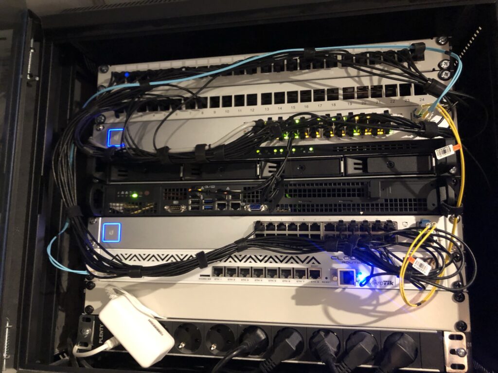
Link is now online! Below is a picture of my 19″ rack at home.

Exploring the CAN bus of my Tesla Model S

The CAN bus of a Tesla vehicle can show some interesting information about the state of different components in the vehicle.

Using a CAN bus cable, Bluetooth adapter and a App on your mobile phone you can gain much more insight on your Tesla vehicle.

I own two Tesla vehicles:

  • S85 from September 2013 (pre face-lift)
  • S100D from September 2018

Somewhere around 2015 Tesla switched to a different connector for the CAN bus so I needed two different cables. I bought my cables in Germany at EMDS.

EMDS also sells a cable for Model 3. I haven’t used this one as I don’t own a Model 3.

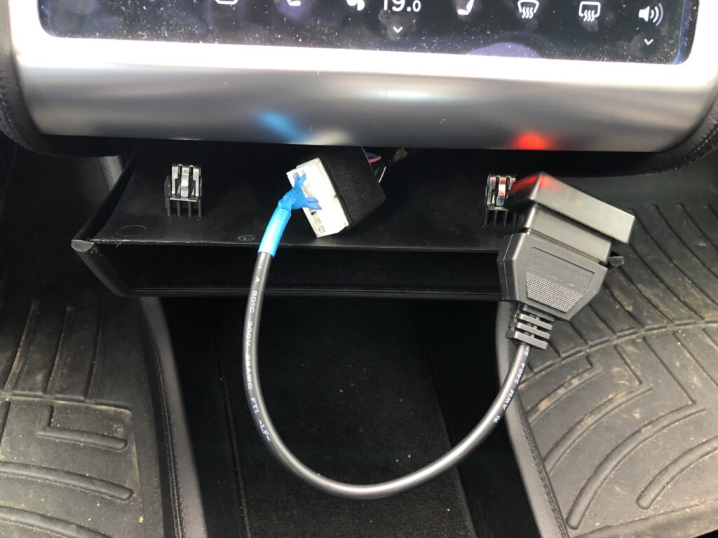
The CAN bus connector in a Model S can be found under the MCU’s main screen in the vehicle. You need to pull down the ‘chubby’ and there you will find the connector:

Cable connected to my Model S85

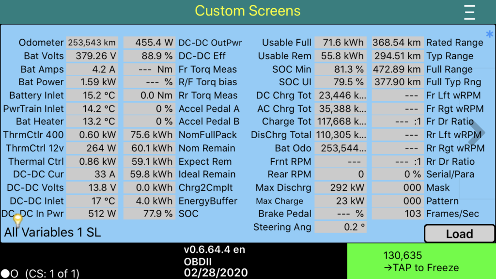
I am using the TM-Spy app on iOS for reading the values on my iPhone.

Screenshot of TM-Spy on iOS

For Android there is Scan My Tesla which also seems to be a very good app. I don’t have an Android device, so I was not able to test it.

I was mainly looking for these values:

  • Usable Full
  • DC Charge Total
  • AC Charge Total

After 253.543km of driving my battery has 75.6kWh of remaining capacity where this was ~81kWh when it was new. (The 85kWh battery was actually a 81kWh battery….)

Tesla also throttles a vehicle’s SuperCharging capabilities after more than X amount (I don’t know the exact value) of DC charging. My car seems to be affected as I SuperCharged a lot.

Charge Total is not a total sum of AC+DC, but from what I’ve read early firmwares did not count AC and DC charging in different values.

Interesting information though! I encourage everybody to use this information to gather more information about their vehicle’s state.

Happy exploring!

Replacing the eMMC in my Tesla Model S

Tesla’s vehicles are awesome. I own a S85 from 2013 and a S100D from 2018. I’ve driven 260.000km and 70.000km with these two vehicles and I love it.

There is however a design flaw in the early Tesla models which can become a very expensive reparation if not performed in time.

Version of of the MCU (Media Control Unit) which was installed up until early 2018 in Tesla S/X runs and is a ticking time bomb.

The problem is the Flash Memory (eMMC) which holds the Operating System of the computer. This wears out over time due to writing data to it.

Writing happens when you use the car. It caches Spotify, Google Maps and many more things. Even when the car is parked the MCU stays running and writes to the eMMC chip.

Eventually this chip will wear out. Before it does it becomes very slow and this results in the MCU becoming super sluggish, unresponsive, the screen reboots at random moments, bluetooth issues, etc, etc.

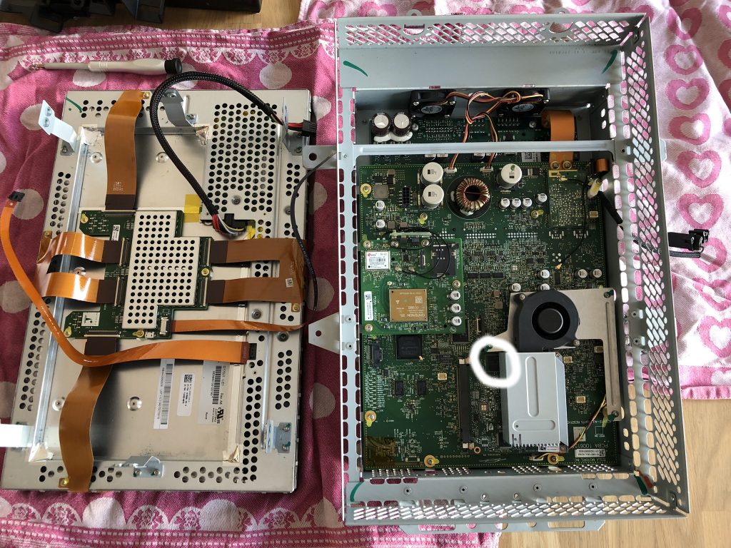
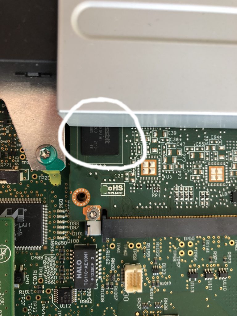
Inside of the Tesla MCU1
The eMMC chip

A lot has been written about this, so I won’t write to much. Short: Tesla will charge you around 2000 EUR/USD for a new MCU.

I choose to replace this eMMC chip myself and this was a lot cheaper! Total cost was <500 EUR.

Around the world there are a couple of companies doing these replacements. I replaced my eMMC chip together with Loek from Laadkabelwinke.nl (Netherlands): https://www.laadkabelwinkel.nl/tesla-mcu1-emmc-vervangen-reparatie

On Tesla Motors Club there are various topics about these replacements, one for example: https://teslamotorsclub.com/tmc/threads/preventive-emmc-replacement-on-mcu1.152489/

I highly recommend everybody with a Model S/X to replace this eMMC chip before it fails.

The chip will wear out and this causes all kinds of problems. I can’t stress this enough. Replace the chip before it’s too late!

In Europe I would recommend to go to Laadkabelwinkel.nl and have them replace the chip.

Enjoy your Tesla!

HAProxy in front of Ceph Manager dashboard

The Ceph Mgr dashboard plugin allows for an easy dashboard which can show you how your Ceph cluster is performing.

In certain situations you can’t contact the Mgr daemons directly and you have to place a Proxy server between your computer and the Mgr daemons.

This can be done easily with HAProxy and the following configuration which assumes that:

  • SSL has been disabled in the Dashboard plugin
  • Dashboard plugin listens in port 8080
  • Mgr is running on the hosts mon01, mon02 and mon03
global
  log         127.0.0.1 local1
  log         127.0.0.1 local2 notice

  chroot      /var/lib/haproxy
  pidfile     /var/run/haproxy.pid
  maxconn     4000
  user        haproxy
  group       haproxy
  daemon

  stats socket /var/lib/haproxy/stats

defaults
  log                     global
  mode                    http
  retries                 3
  timeout http-request    10s
  timeout queue           1m
  timeout connect         10s
  timeout client          1m
  timeout server          1m
  timeout http-keep-alive 10s
  timeout check           10s
  maxconn                 3000
  option                  httplog
  no option               httpclose
  no option               http-server-close
  no option               forceclose

  stats enable
  stats hide-version
  stats refresh 30s
  stats show-node
  stats uri /haproxy?stats
  stats auth admin:haproxy

frontend https
  bind *:80
  default_backend ceph-dashboard

backend ceph-dashboard
  balance roundrobin
  option httpchk GET /
  http-check expect status 200
  server mon01 mon01:8080 check
  server mon02 mon02:8080 check
  server mon03 mon03:8080 check

You can now point your browser to the URL/IP of your HAProxy and use your Ceph dashboard.

In case a Mgr machine fails the health checks of HAProxy will make sure it fails over to on of the other Mgr daemons.

VXLAN with VyOS and Ubuntu 18.04

VXLAN

Virtual Extensible LAN uses encapsulation technique to encapsulate OSI layer 2 Ethernet frames within layer 4 UDP datagrams. More on this can be found on the link provided.

For a Ceph and CloudStack environment I needed to set up a Proof-of-Concept using VXLAN and some refurbished hardware. The main purpose of this PoC is to verify that VXLAN works with CloudStack, Ceph and Ubuntu 18.04

VyOS

VyOS is an open source network operating system based on Debian Linux. It supports VXLAN, so using this we were able to test VXLAN in this setup.

In production a other VXLAN capable router would be used, but for a PoC VyOS works just fine running on a regular server.

Configuration

The VyOS router is connected to ‘the internet’ with one NIC and the other NIC is connected to a switch.

Using static routes a IPv4 subnet (/24) and a IPv6 subnet (/48) are routed towards the VyOS router. These are then splitted and send to multiple VLANs.

As it took me a while to configure VXLAN under VyOS

I’m only posting that configuration.

interfaces {
    ethernet eth0 {
        address 31.25.96.130/30
        address 2a00:f10:100:1d::2/64
        duplex auto
        hw-id 00:25:90:80:ed:fe
        smp-affinity auto
        speed auto
    }
    ethernet eth5 {
        duplex auto
        hw-id a0:36:9f:0d:ab:be
        mtu 9000
        smp-affinity auto
        speed auto
        vif 300 {
            address 192.168.0.1/24
            description VXLAN
            mtu 9000
        }
    vxlan vxlan1000 {
        address 10.0.0.1/23
        address 2a00:f10:114:1000::1/64
        group 239.0.3.232
        ip {
            enable-arp-accept
            enable-arp-announce
        }
        ipv6 {
            dup-addr-detect-transmits 1
            router-advert {
                cur-hop-limit 64
                link-mtu 1500
                managed-flag false
                max-interval 600
                name-server 2a00:f10:ff04:153::53
                name-server 2a00:f10:ff04:253::53
                other-config-flag false
                prefix 2a00:f10:114:1000::/64 {
                    autonomous-flag true
                    on-link-flag true
                    valid-lifetime 2592000
                }
                reachable-time 0
                retrans-timer 0
                send-advert true
            }
        }
        link eth5.300
        mtu 1500
        vni 1000
    }
    vxlan vxlan2000 {
        address 109.72.91.1/26
        address 2a00:f10:114:2000::1/64
        group 239.0.7.208
        ipv6 {
            dup-addr-detect-transmits 1
            router-advert {
                cur-hop-limit 64
                link-mtu 1500
                managed-flag false
                max-interval 600
                name-server 2a00:f10:ff04:153::53
                name-server 2a00:f10:ff04:253::53
                other-config-flag false
                prefix 2a00:f10:114:2000::/64 {
                    autonomous-flag true
                    on-link-flag true
                    valid-lifetime 2592000
                }
                reachable-time 0
                retrans-timer 0
                send-advert true
            }
        }
        link eth5.300
        mtu 1500
        vni 2000
    }
}

VLAN 300 on eth5 is used to route VNI 1000 and 2000 in their own multicast groups.

The MTU of eth5 is set to 9000 so that the encapsulated traffic of VXLAN can still be 1500 bytes.

Ubuntu 18.04

To test if VXLAN was actually working on the Ubuntu 18.04 host I made a very simple script:

ip link add vxlan1000 type vxlan id 1000 dstport 4789 group 239.0.3.232 dev vlan300 ttl 5
ip link set up dev vxlan1000
ip addr add 10.0.0.11/23 dev vxlan1000
ip addr add 2a00:f10:114:1000::101/64 dev vxlan1000

That works! I can ping 10.0.0.11 and 2a00:f10:114:1000::1 from my Ubuntu 18.04 machine!